Platforms/Import into Software Platform/
Import Generated PLC in Mitsubishi Melsoft Navigator and GX Works 3

Introduction
MELSOFT Navigator and GX Works3 are part of the integrated software suiteMELSOFT iQ Worksdeveloped by Mitsubishi Electric Corporation, one of the best global manufacturers of electrical and electronic equipment. The software serves as a integrated engineering toolset, enabling users to efficiently develop, debug, and maintain their automation systems.
MELSOFT Navigator is specifically designed to manage the system level design and acts as the interface between each software contained inMELSOFT iQ Works. MELSOFT Navigator offers a user-friendly interface with various intuitive features, making it accessible to both novice and experienced programmers.
GX Works3 is a powerful software suite for programming and configuring Mitsubishi Electric PLCs. It provides a comprehensive set of powerful tools for efficient PLC development and maintenance.
This page provides a detailed tutorial on how to import a PLC created with PLCCreator in Mitsubishi MELSOFT Navigator and GX Works3. You can even use this guide to restore the iQ-R PLC from saved exports in the form of .aml files for the PLC stations, and .csv files for global comments and labels.
The steps presented in this procedure describe the import ofEx4_Single_FieldbusPLC from our example PLCs found onMy PLCspage. Please note that the names of stations, station .aml filenames and module names are related to this example PLC project, and they can be different in your PLC projects.
1.
Download Project from PLCCreator
In some cases on mobile devices or smaller screens, if the button is not visible, you may first click the toolbar menu button to open the PLC details toolbar.
Unzip the file preferably in the separate folder.
2.
Create New Workspace
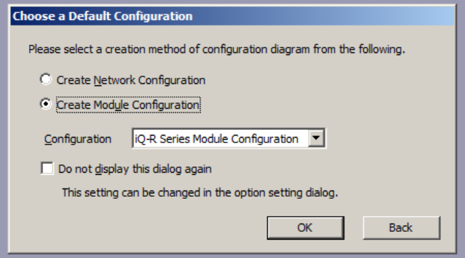
Open MELSOFT Navigator and create a new workspace. When the following dialog appears, make sure you have selected the configuration method "Create Module Configuration" with the configuration "iQ-R Series Module Configuration".
3.
Import Main Station - Open File Import Dialog
On the workspace docking window find and right-click the "Module Configuration". Point to "Open Data in Another Format", then to "AutomationML Format" and click "Open Electrical CAD File...". If a dialog appears, confirm it affirmatively.
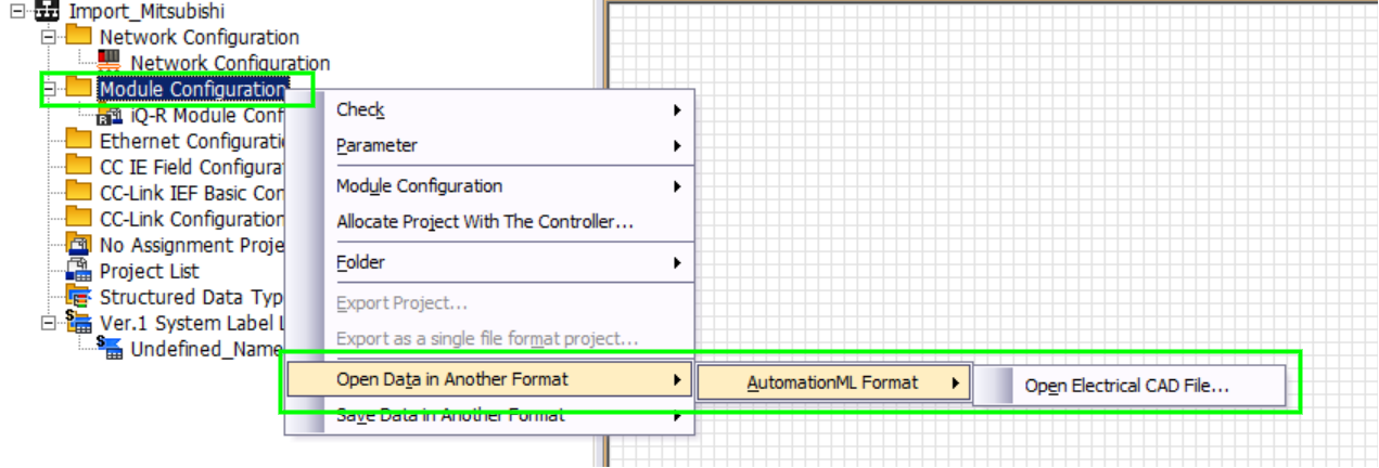

If a dialog appears, confirm it affirmatively.
4.
Import Main Station - Select Station File
Point to the directory where you have unzipped the zip file and select the.amlfile that starts with"R0_CPU"and click "Open". The station import will start. If a dialog appears, confirm it affirmatively.

5.
Create GX Works3 Project for Main Station
On the station configuration, find the CPU module and double-click it. A new GX Works3 project dialog will appear. For "Project Name" it is recommended to set the PLC name you have set in PLCCreator, in this instance "Ex4_Single_Fieldbus", and click "Create".


Starting from step 6 to step 16, the import of distributed stations and fieldbus network is described. If your project has main station only, go ahead directly to17. Check System Configuration.
6.
Import Distributed Stations
Repeat the steps3,4and5for each distributed station in the project. We will name these steps6a,6band6c.
The .aml filename for the distributed station has the following format:
RX_FBS#fieldbus_name#_STA#X_station_name.aml
where:
- "X"is the distributed station number during PLC generation. It should always be greater than 0. Please note that each .aml file starts with"RX_"and it is recommended to be imported in that order.
- The string between"FBS#"and "#" is the name of the fieldbus that the distributed station is connected to. In this instance, it is the default fieldbus "f1" for the single fieldbus architecture.
- The string after"STA#X_"is the name of the station. This name is created by concatenation of the words "Rack_", the name of the group in the signal/device IO list to which signals/devices from the station are assigned to, and the incremental counter that is the creation order number of racks that group. In this instance, we have "Rack_Section2_1".
6a.
Import Distributed Station - Open File Import Dialog
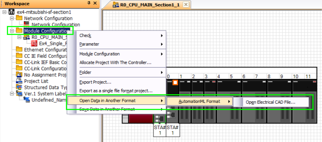
This step is completely the same asstep 3performed earlier: on the workspace docking window, find and right-click the "Module Configuration". Point to "Open Data in Another Format", then to "AutomationML Format", and click "Open Electrical CAD File...". If a dialog appears, confirm it affirmatively.

6b.
Import Distributed Station - Select Station File
Point to the directory where you have unzipped the zip file and select the.amlfile that starts with"RX_FBS#", in this instance "R1_FBS#", and click "Open". The station import will start. If a dialog appears, confirm it affirmatively.

6c.
Create GX Works3 Project for Distributed Station
On the station configuration find the communicationinterface module. Please note it has "CPU" as slot name. Double click it and a new GX Works3 project dialog will appear. For the "Project Name" it is recommended to set either the rack name given by PLCCreator, in this instance "Rack_Section2_1", or the fieldbus name and station order number, in this instance "f1_STA1". Click "Create".


7.
Open "Network Configuration"
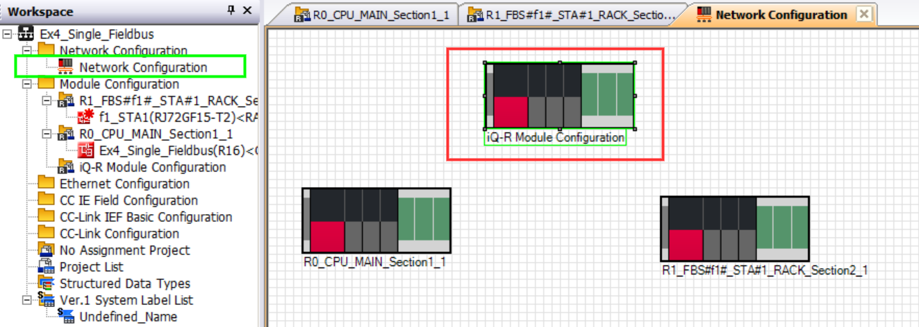
On the workspace docking window, find and double-click the "Network Configuration". You will see the imported stations overlapping each other, you can rearrange them for better visibility. If you see "iQ-R Module Configuration" station, as shown with red rectangle on Figure 8, you can remove it and close its tab on the tab bar. If your PLC has multiple fieldbus architecture arrange the stations with the same fieldbus (same RX_FBS#fieldbus_name# prefix), in the groups for better visibility.

8.
Add "CC Link IE Field" Fieldbus Network
On the module list docking window, expand the "Network" group (1), select the "CC Link IE Field" module (2), and drag it onto the network configuration worksheet (3). Since we have a single fieldbus architecture, we will have one network, "Network No.1" (3), that corresponds to fieldbus "f1" from our PLCCreator project.


9.
Open Network Properties
Right-click network module (1) and click "Properties" (2).


10.
Rename Network
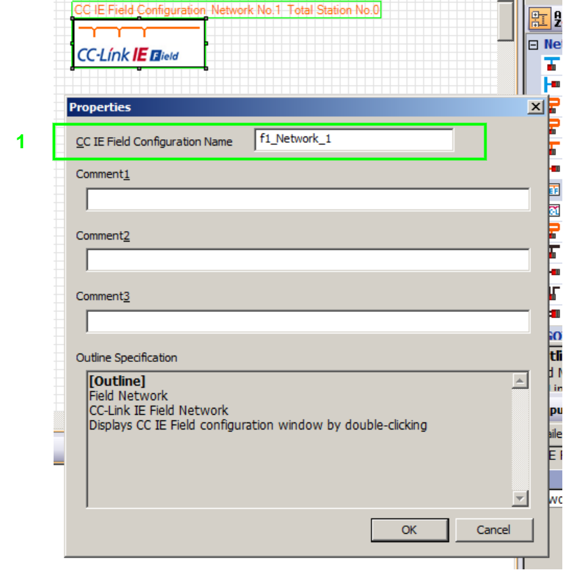
Locate "CC IE Field Configuration Name" (1). Initially it has a generic name, and it is recommended to be renamed to be easily distinguished among the other networks. It is recommended that the network name should contain the names of both corresponding networks: the PLCCreator fieldbus name and MELSOFT network number. The recommended naming format can be following:
"fieldbus_name"_Network_"network_number"
In this instance, considering that "Network_1" corresponds to the fieldbus "f1" in the PLCCreator project, the recommended name for our network would be "f1_Network_1".

11.
Connect Fieldbus Master Station to the Network
In PLC systems generated by PLCCreator, the fieldbus master modules are always located in the Main Rack (CPU station).
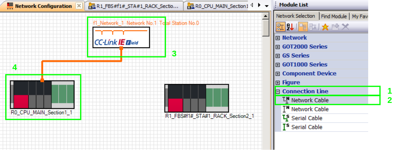
On the module list docking window, expand the "Connection Line" group (1), select the "Network Cable" module (2), drag it over and connect it to the "CC Link IE Field" module on the network configuration worksheet (3). Click on the lower end of the "Network Cable" and drag it over and connect it to the CPU station (4).

12.
Find Fieldbus Master Module and Set the Station Type
Double-click the CPU station, or just click its tab on the tab bar. Locate the CC Link IE Field communication module that has fieldbus master capability. In PLC systems generated by PLCCreator, the fieldbus master modules always occupy the slots right after the CPU slot. The module name follows the naming convention:
"fieldbus_name"_Master_"slot_number"
where:
"fieldbus_name"is the name of the fieldbus. In case of Single Fieldbus Architecture it is "f1" by default.
In case of Multiple Fieldbuses Architecture it shall be one of the fieldbuses registered on My Fieldbuses page, and referenced in the "Fieldbus" column of the uploaded IO list.
- "slot_number"is the number of the physical slot occupied by the master module set by PLCCreator. Please note it is not always equal with the slot number assigned by the software platform, however this is not affecting the overall project consistency because it is unique on rack level.
In this instance, theEx4_Single_FieldbusPLC is based on Single Fieldbus Architecture , so the fieldbus name is "f1" and the fieldbus master module name is "f1_Master_2" (1). Set its "Station Type" to "Master Station" (2) as shown onFigure 13.
In this system we have only one master. However, in systems with Multiple Fieldbuses Architecture there will be 2 or more fieldbus master modules, and it matters which fieldbus master module to which network is assigned. In the CC Link protocols, networks are identified by the network number, which is shown inside the title found above the network module (3). It is recommended to keep a record of correspondence between fieldbus names from PLCCreator and network numbers from Melsoft Navigator:
In this instance, we have fieldbus"f1"corresponding to"Network 1".


13.
Connect Fieldbus Master Module to the Network
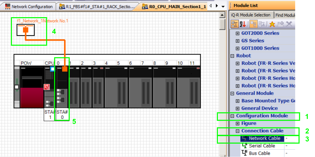
To connect fieldbus master module to "Network 1" (fieldbus "f1"), scroll down to the bottom of the module list docking window, expand the "Configuration Module" group (1), then the "Connection Cable" group (2), select the "Network Cable" module (3), and connect it to the "CC Link IE Field" module (4). Drag and connect the other end to the "f1_Master_2" module (5).

14.
Adding Distributed Station to the Network
InStep 12, we have already assigned the fieldbus "f1" from the PLCCreator project to "Network 1". This implies that all stations whose file names have"_FBS#f1#"shall be connected to "Network 1".
Repeat the steps11,12and13for each distributed station in the project. We will name these steps14a,14band14c. In this instance, we should only connect the "R1_FBS#f1#_STA#1_Rack_Section2_1".
14a.
Connect Distributed Station to the Network
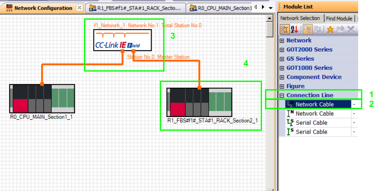
On the workspace docking window, double-click the "Network Configuration" or simply click on its tab on the tab bar. On the module list docking window, expand the "Connection Line" group (1), select the "Network Cable" module (2), and connect the "CC Link IE Field" module (3) to the "R1_FBS#f1#_STA#1_Rack_Section2_1" station (4).

14b.
Find Fieldbus Interface Module
Rack_"group_name"_"group_rack_count_number"
where:
- "group_name"is the name of the group whose devices/signals shall be wired to this station. The group is set on My Groups page and referenced in the uploaded IO list, in this instance onUpload IO Signalspage.
- "group_rack_count_number"is the unique incremental number that identifies the station within a group. Please note there can be more than one rack per group.
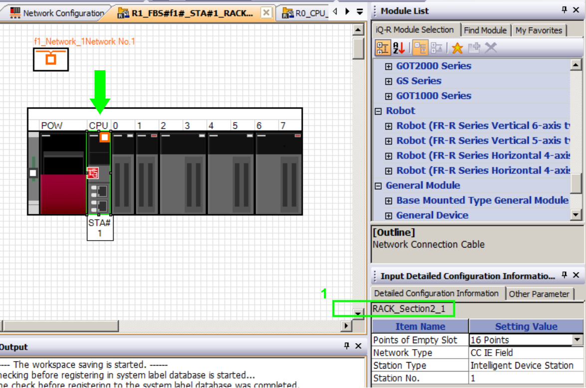
In this instance the name of the interface module is "Rack_Section2_1" (1).

14c.
Connect Fieldbus Interface Module to the Network
On the module list docking window, scroll down to the bottom, expand the "Configuration Module" (1), then the "Connection Cable" group (2), select the "Network Cable" module (3). Connect it to the "CC Link IE Field" module (4) and the "Rack_Section2_1" module (5).


15.
Open "CC IE Field" Network Configuration
On the workspace docking window expand the "CC IE Field Configuration" group (1) and double-click the currently edited network, in this instance "f1_Network_1" (2). The "CC IE Field Configuration" tab will open. On the upper part of the configuration window is the network configuration table (3) and on the lower part is the network topology (4).


16.
Copy "CC IE Field" Configuration from PLCCreator to MELSOFT Navigator
In PLCCreator go toPLC Detailspage and scroll down to the fieldbus group box that corresponds with the currently edited network, in this instance there is only 1 fieldbus network with master module "f1_Master_2" and find the "CC Link IE Network Configuration" table (1). Copy/Paste the "Start" and "End" addresses both for "RX/RY" (3) and "RWr/RWw" (3) setting to the "CC IE Field" configuration table (2) for each distributed station in the network. Both tables shall have the same values in each cell.


In case of Multiple Fieldbuses Architecture , the steps from8. Add "CC Link IE Field" Fieldbus Networkto16. Copy "CC IE Field" Configuration from PLCCreator to MELSOFT Navigatorshould be performed for each fieldbus in the project.
17.
Check System Configuration
On the workspace docking window right-click the project title, in this instance "Ex4_Single_Fieldbus", point to the "Check" and click "System Configuration". The system will perform its checking and there shall be no errors. If a dialog appears, confirm it affirmatively.


18.
Reflect Parameters
On the workspace docking window right-click the project title, in this instance "Ex4_Single_Fieldbus", Point to the "Parameter" and click "Batch Reflect". The parameter batch reflection dialog appears, and press "Execute Reflection". The process of reflection can take several minutes and at the end there shall be no error reported in the output window.


The steps from 19 onwards are related to GX Works3.
19.
Open GX Works3 Project for the CPU Station
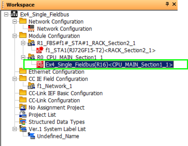
On the workspace docking window, find and double-click the GX Works3 project of the CPU station (1), in this instance, "Ex4_Single_Fieldbus". The GX Works3 project will open.

20.
Check Parameters
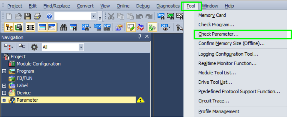
On the main menu, click "Tool", and then click "Check Parameter...".

21.
Find Fieldbus Master Module
Expand the modules group (1). In the PLC configurations generated by PLCCreator the fieldbus master modules are always located between the CPU module and IO modules. Double-click the "Network 1" master module, which in this instance is the module with module address 0 (2). The module settings window will open. Click on "Required Settings" (3) and ensure that the "Station Type" is "Master Station", and the "Network No." corresponds to the network we are working on, in this instance, "1" (4). If there are multiple master modules for multiple fieldbus architectures, the network number for each master module must be different.


22.
Open Master Refresh Settings
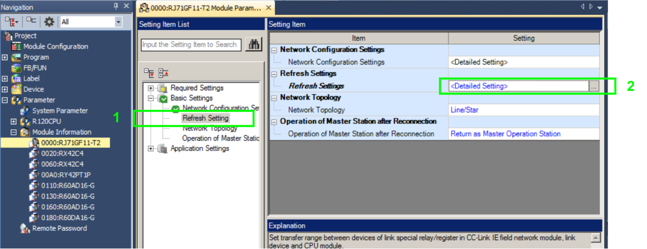
Click "Basic Settings" (1), and then double-click on "<Detailed Setting>" of the "Refresh Settings" on the right panel (2). The "Refresh Settings" parameter window will open.

23.
Copy Master Refresh Settings from PLCCreator to Fieldbus Master Module
In PLCCreator go toPLC Detailspage and scroll down to the fieldbus group box that corresponds with the currently edited network and find the "Master Refresh Settings" table (2). Set or copy/paste following data to the "Refresh Setting" table:
- Set the "Device Name" (3) and corresponding "Start" and "End" addresses (4) on the Link Side
- Set "Specify Device" for the "Target" and set the "Device Name" (5) with corresponding "Start" addresses (6) on the CPU Side
Both tables starting from row "No. 1" shall have the same values in each cell.
Click "Check" (7) and then "Apply" (8).


In the case of Multiple Fieldbuses Architecture , the steps21,22and23should be performed for each fieldbus in the project.
24.
Import Common Device Comment - Open File Import Dialog
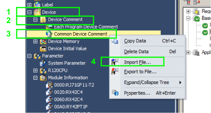
On the navigation docking window expand "Device" (1), then expand "Device Comment" (2), then right-click "Common Device Comment" (3) and click the "Import File..." (4).

25.
Import Common Device Comment - Select Comment File
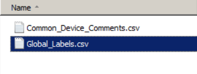
Point to the directory where you have unzipped the zip file and select theCommon_Device_Comments.csvfile and click "Open". The common device comment import will start. If a dialog appears, confirm it affirmatively.

26.
Import Global Label - Open File Import Dialog
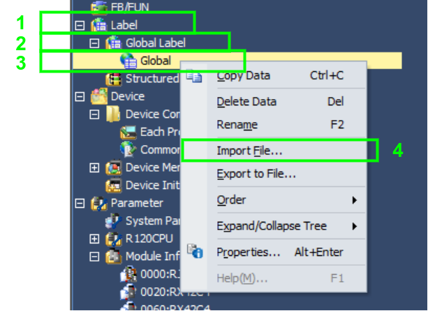
On the navigation docking window expand "Device" (1), then expand "Device Comment" (2), then right-click "Global Label" (3) and click the "Import File..." (4).

27.
Import Global Label - Select Label File
Point to the directory where you have unzipped the zip file and select theGlobal_Label.csvfile and click "Open". The global label import will start. If a dialog appears, confirm it affirmatively.
